TEG-Tester

Measuring devices for thermoelectric generators and Peltier elements

Description

To the point

In recent years, there has been an increasing demand for technologies for the use of renewable energies as well as for optimization possibilities for the most effective use of fossil resources.
The physical phenomenon of thermoelectricity offers the possibility of converting thermal energy directly into electricity and thus represents an opportunity to utilize unused waste heat, for example from industrial processes, the exhaust system of vehicles or even body heat.

The Linseis TEG tester is a measuring system for characterizing the efficiency of thermoelectric generators (TEGs) and Peltier elements under variable conditions.
Depending on the mode used, either a temperature gradient or an external current is applied to the module.
If TEGs are measured, a known heat flow (determined with maximum accuracy by means of reference block measurement) is impressed through the TEG and the electrical output power can be determined using various methods (CC, CV, FOC, MPPT, P&O).

The generated voltage and current are sampled at different points in less than 10 ms to obtain the I-V curves or to operate the TEG under dynamic load.
Therefore, it is possible to calculate the efficiency and track the maximum power point using the disturbance and observation method.

If, on the other hand, a known electrical current is applied to the module, the cooling capacity or the generated heat flow can be determined via the meter bars of the TEG tester.


Applications:

  • Performance testing of thermoelectric modules
  • Evaluation of maximum energy generation and conversion efficiency
  • Long-term tests under load and temperature changes


Properties:

  • Automatic mechanical loading with pressure equalization
  • Various operating modes (CC, CV, FOC, MPPT, P & O)

Measuring principle

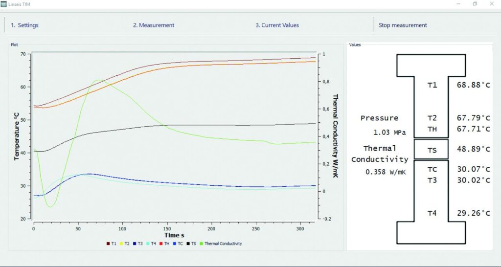
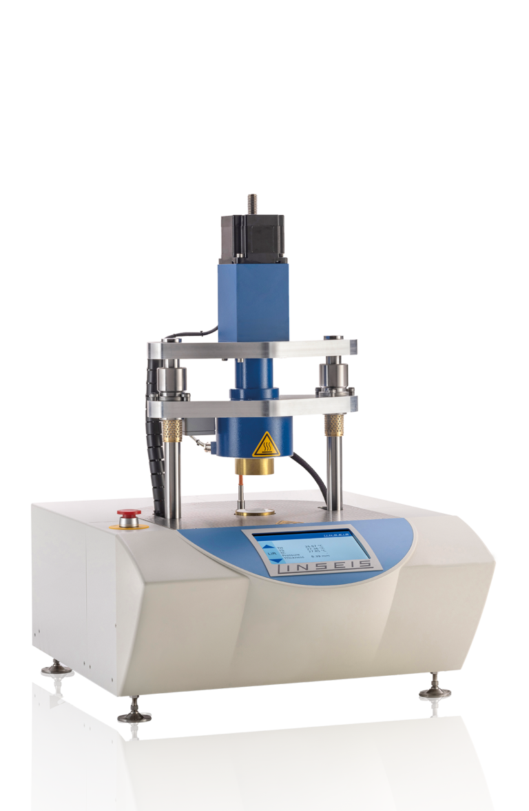
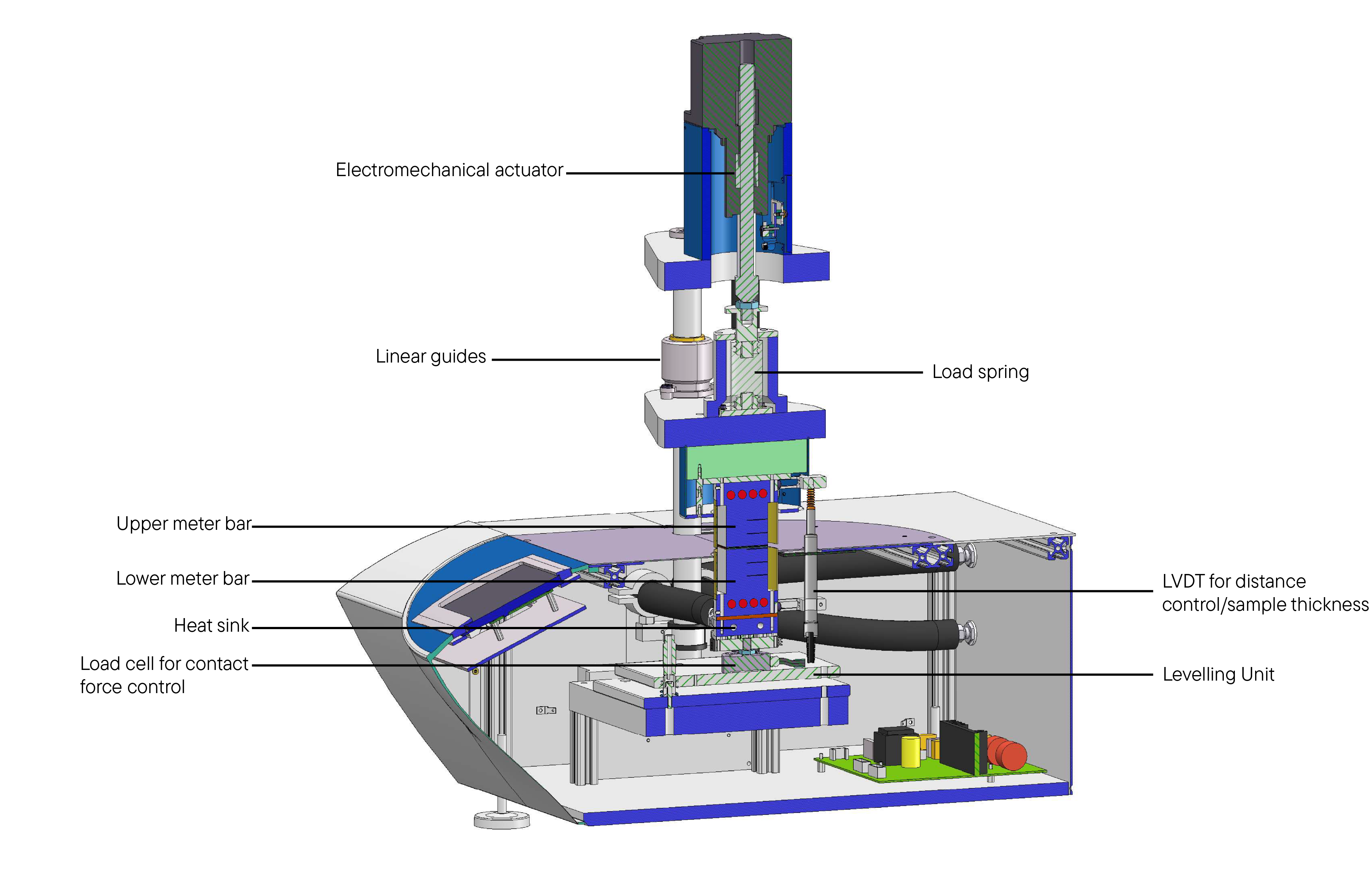
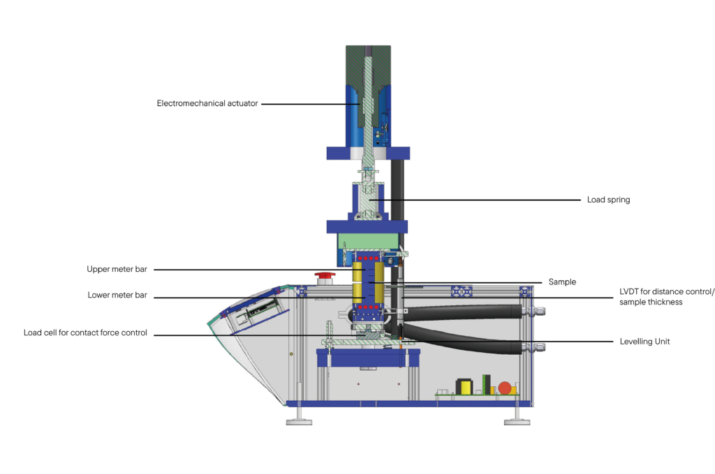
A sample is positioned between a hot and a cold measuring rod, whereby the hot measuring rod is connected to a controlled heating stage and the cold measuring rod is connected to a thermostatically controlled, liquid-cooled heat sink. The contact pressure on the sample can be automatically adjusted via an integrated electrical actuator (with regard to pressure stability over temperature). The sample dimension (thickness) can either be entered manually or measured (and controlled) using an integrated LVDT sensor. The heat flow through the sample and the temperatures on the hot and cold sides at the top and bottom of the module are continuously monitored using several temperature sensors located at a known distance inside each measuring rod. 
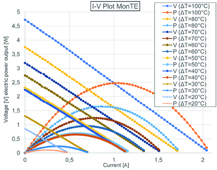
The thermoelectric conversion efficiency η of the investigated TEG can be obtained by adjusting the thermal power in relation to the generated electrical power. 
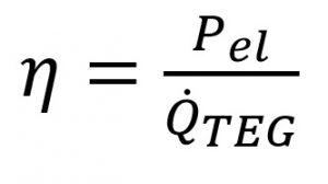
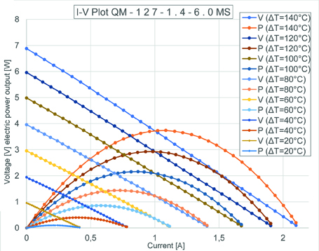
Where Pel is the electrical power generated in watts and QTEG is the thermal power, also in watts. Since the electrical power “V” times “I” varies with the load it controls, the maximum output power (Maximum Power Point) can be determined using a variable load resistor in the device.

Unique features

Automatic mechanical load with pressure equalization:
Ensures stable measuring conditions

Various operating modes:
Including CC, CV, FOC, MPPT,
P & O for a wide range of testing
options

Fast sampling time:
Detection of the generated
voltage and current in less
than 10 ms

Temperature range:
Measurements from
-20°C to 300°C possible

Long-term tests:
Enables tests under load
and temperature changes
for reliable results.

Service hotline

+01 (609) 223 2070


+49 (0) 9287/880 0

Our service is available Monday to
Thursday from 8 am to 4 pm
and Friday from 8 am to 12 pm.

We are here for you!

Specifications

Black on white

MODEL

TEG-TESTER

Sample size:Round: ø 20 mm, 25 mm, 40 mm, 60 mm
Rectangular: 20 mm x 20 mm, 25 mm x 25 mm, 40 mm x 40 mm
Other sizes on request
Sample thickness:up to 25 mm
Accuracy of thickness:+/- 0.10 % at 50% tensile force
+/- 0.25 % at 100% tensile force
Temperature range:RT up to 300°C (on the hot side) / -20 °C up to 300 °C
Temperature accuracy:0.1°C
Voltage range:0 – 12 V (DC)
Accuracy of voltage:0.3 %
Voltage resolution:1.6 µV
Amperage:0-3 A (DC)
Current accuracy:0.3 %
Current resolution:1 µA
Heat dissipation:up to 36 W
Rating:Heat Flow
Average Seebeck coefficient
Average thermal conductivity
Average module resistance
Power output
Conversion efficiency of the module
Reference block material:Aluminium, brass, copper (others on request)
Temperature sensors:Thermocouple type E
Clamping force:2 kN to 5 kN (electric drive)
Heating power:1.0 kW
Intracooler
Cooling capacity:1.0 kW (10 °C) / 0.5 kW (-20 °C)
Pump capacity:27 l/min / 0.7 bar
Tank capacity:3.8 l up to 7.5 l
Refrigerant used:R449 Liquid

Data sheet

Detailed view of the measuring body

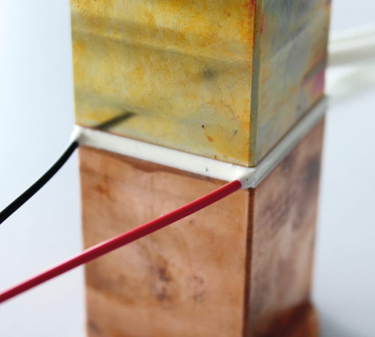
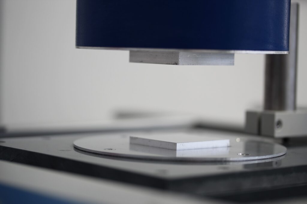
Thermoelectric module between two meter bars.

Software

Making values visible and comparable

The brand new Rhodium software significantly improves your workflow as the intuitive data processing requires minimal parameter input. AutoEval provides the user with valuable guidance in the evaluation of standard processes such as the determination of thermal impedance or thermal conductivity.

  • Software packages are compatible with the latest Windows operating system
  • Set up menu items
  • Software-controlled heating, cooling or dwell time segments
  • Evaluation of maximum energy generation and conversion efficiency
  • Long-term tests under load and temperature changes
  • Software-controlled thickness determination, force / pressure adjustment
  • Simple data export (measurement report)
  • All specific measurement parameters (user, laboratory, sample, company, etc.)
  • Optional password and user levels
  • Multiple language versions such as English, German, French, Spanish, Chinese, Japanese, Russian, etc. (user selectable)

Applications

Application example: Temperature-dependent maximum power point tracking of a TEG (MonTE)

Electrical characterization diagrams (V-I and P-I curves from open-circuit Voc to short-circuit Isc) of a standard Bi2Te3 thermoelectric module (monTE) for different temperature gradients from ΔT = 20K to 100K.

Application example: Temperature-dependent maximum power point tracking of a TEG (QM-127-1.4-6.0MS) Electrical characterization diagrams (V-I and P-I curves from open-circuit Voc to short-circuit Isc) of a standard Bi2Te3 thermoelectric module (QM-127-1.4-6.0MS) for different temperature gradients from ΔT = 20K to 140K.

Well informed

Downloads

Everything at a glance