Table of Contents
Scientific Definition
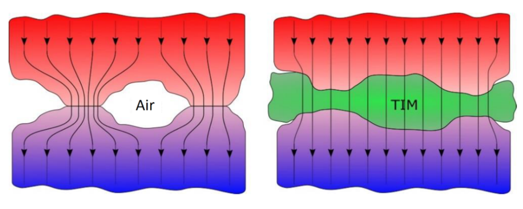
In electronic devices the thermal management is a crucial performance factor since the overheating of components can lead to failure. The task here is to transfer the generated heat from the electronics to cooling devices, i.e. heat sinks or heat dissipators. However, even the most efficient heat sink cannot dissipate heat optimally if the contact surfaces do not manage the necessary heat transfer. Despite modern manufacturing processes a certain surface roughness remains on which microscopic air inclusions occur.

Thermal interface materials, shortly TIMs, are designed to fill those voids between components so that the heat transfer is improved significantly. This means also, that the contact resistance between the heat generating component and the heat sink should be lowered using the TIM.
Thermal properties of TIM´s
The performance of a TIM depends thus on its thermal properties, the most common properties used in industry which are listed in data sheets are thermal conductivity and thermal impedance. Advantageous of having a look onto the thermal impedance of a TIM is that is also reflects the conditions of an application, as it accounts also e.g. the thickness of the material and clamping pressure.
The thermal conductivity is a material-specific property and describes the ability of a material to conduct heat. This means that for thermal management it is advantageous to use a TIM with a high thermal conductivity to improve the cooling effect.
Related to this is the thermal resistance which is the ability to resist a heat flow. In contrast to the thermal conductivity, the thermal resistance depends on the thickness of the material. So, for a constant thermal conductivity it means that the thicker the material, the higher the thermal resistance.
Thermal design and the choice of a TIM must consider not only the thermal conductivity of the material but also the contact resistance between the heat generating component, the TIM and the heat sink. Here, the thermal impedance comes into play: it describes the sum of the thermal resistance and the contact resistance, i.e. it is the total opposition that an assembly, which is the material and the material interfaces, presents to the flow of heat.
This means that ideally, the TIM material has a high thermal conductivity and at the same time possesses a low thermal impedance.
Summarized properties:
- Thermal conductivity
- Thickness of the material contact pressure
- Thermal resistance
- Contact resistance
Measurement method
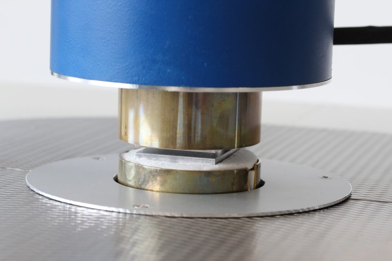
Thermal impedance measurements are typically performed using a TIM-Tester which confirm the norm ASTM D5470. It uses a steady-state method where a specimen is clamped between a heated and a cooled meter bar. The temperature gradient over the specimen, the resulting heat flux together with the test surface area, which has the same size as the material, are then used for the thermal impedance calculation. The thermal impedance thus measures the specimen thermal resistance plus the interfacial thermal resistance between the material and the test surfaces and is denoted by θ and given in the unit of m2∙K/W.

As the contact resistance varies depending on the specimen surface and the pressure applied by the test surfaces onto the tested material, the pressure is recorded by the TIM-Tester. The thickness of the specimen is also measured
With the TIM-Tester one can determine the apparent thermal conductivity as well, so the thermal conductivity specific to the test conditions. For this one needs to exclude the interfacial thermal resistance. This can be done by firstly measuring and plotting the thermal impedance in dependence on different specimen thicknesses. This results in a straight line whose inverse of the slope is the apparent thermal conductivity and the intercept at thickness zero corresponds to the contact resistance at the two test surfaces.

