Measuring devices for thermoelectrics
Waste heat recovery / Thermoelectric generators (TEG) / Peltier elements / Sensors
Linseis electrical properties series
Seebeck, Peltier and Thomson effect
Thermoelectricity generally describes the reciprocal influence of temperature and electricity in a material and is based on three fundamental effects: the Seebeck effect, the Peltier effect and the Thomson effect. The Seebeck effect was discovered in 1821 by Thomas J. Seebeck, a German physicist, and describes the occurrence of an electric field when a temperature gradient is applied in an electrically insulated conductor. The Seebeck coefficient S is defined as the quotient of negative thermoelectric voltage and temperature difference and is a purely material-specific quantity that is usually specified in the unit µV/K.
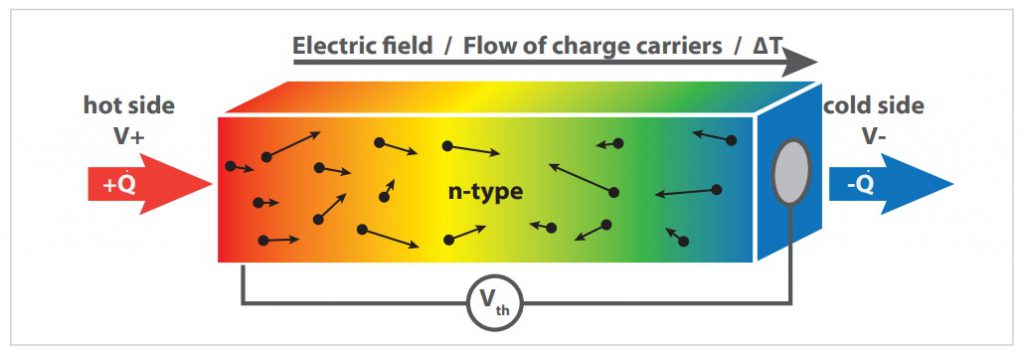
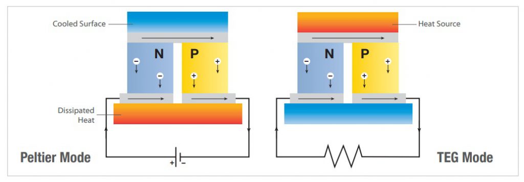
In the opposite case, this effect, then called the Peltier effect, causes a temperature gradient to appear when an external current is applied to the conductor. This phenomenon is due to the different energy levels of the conduction bands of the materials involved. When transferring from one material to another, the charge carriers must either absorb energy in the form of heat, causing the contact point to cool down, or they can release energy in the form of heat, causing the contact point to heat up.
In view of the increasing scarcity of fossil fuels and the latest findings on global warming due to rising carbon dioxide emissions, the field of thermoelectricity has once again become the focus of public interest due to its effective use of waste heat. The aim is to use the waste heat from heat engines, such as cars or conventional power plants, by means of thermoelectric generators (TEG) in order to increase their efficiency. However, efficient thermoelectric materials are also of great interest for cooling applications using the Peltier effect, such as the thermostatting of temperature-critical components in lasers.
The thermoelectric conversion efficiency of a material is usually compared using the dimmingless figure of merit ZT. This is calculated from the thermal conductivity, the Seebeck coefficient and the electrical conductivity.
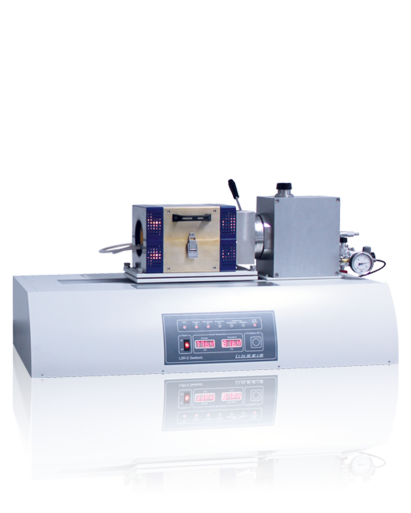
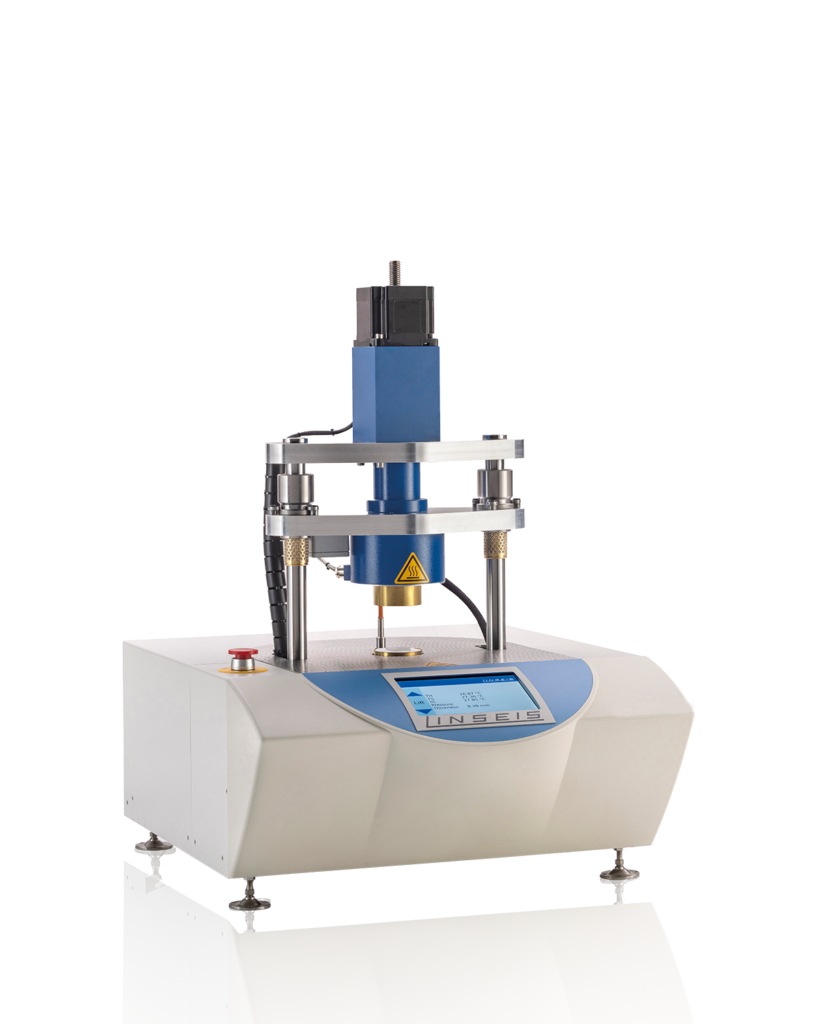
In order to do justice to this development, we have developed an instrument for simple and extremely precise material characterization. The Linseis LSR-3 can determine both the Seebeck coefficient and the electrical resistance of a sample in a temperature range from -100° C to 1500°C.
Are you interested in a electrical property measuring device?
Would you like to carry out a
sample measurement?
Contact us today!

Erika
Tel.: +1 (609) 223 2070
+49 (0) 9287/880 0
[email protected]
Overview of applications and samples
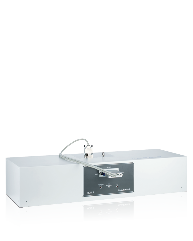
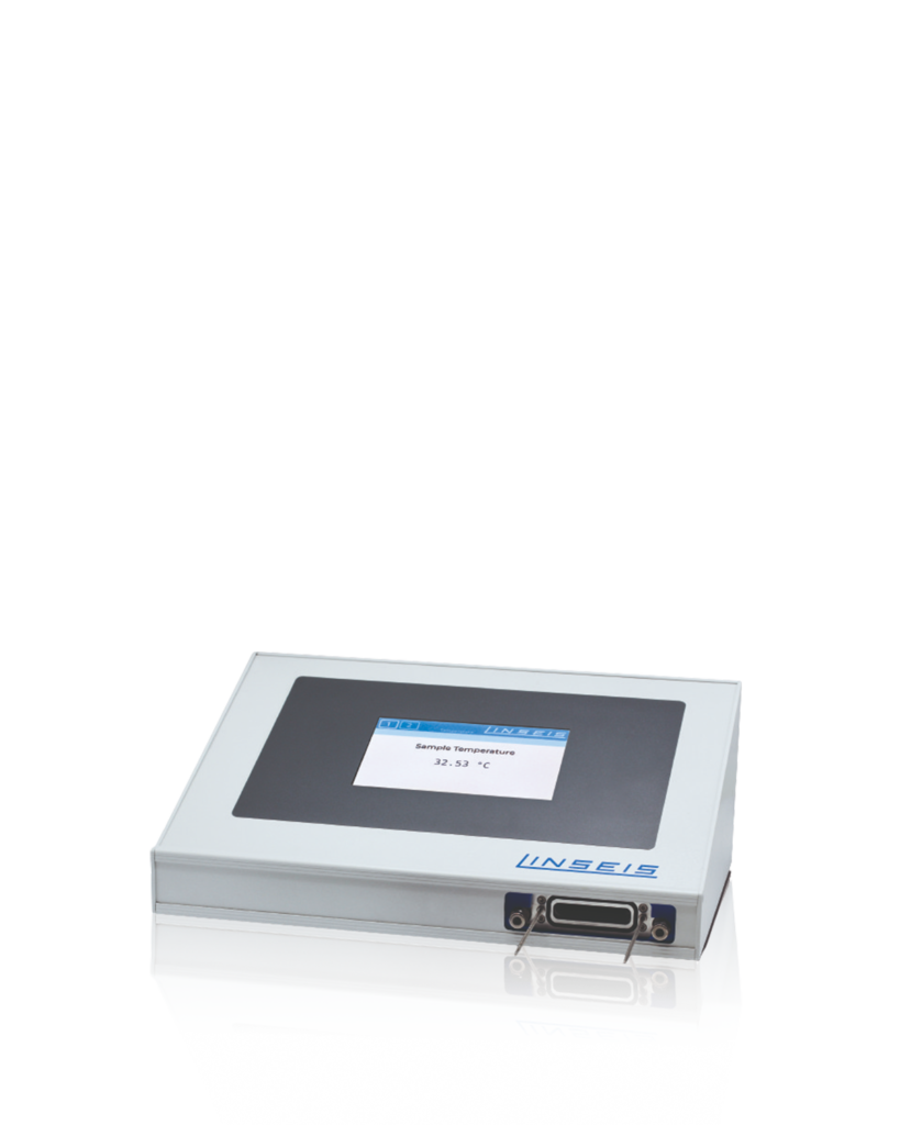
The following is an overview of the various measuring instruments for thermoelectrics. This should serve as a guide for you. If you have any questions about a measurement or a material, you can send us a message at any time using the contact form.

Green: Measurement possible

Yellow: Measurement possibly possible

Gray: Measurement not possible
MODEL | LSR-3 | LSR-4 | LZT | HCS | TFA |
|---|---|---|---|---|---|
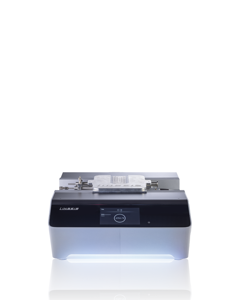
| Info | Standard Plattform | Harman upgrade for LSR-3 | Combination of LSR-3 + LFA 1000 | additionally with Hall constant | Thin films on Linseis-chip |
| Measurements | |||||
| Seebeck coefficient |  |  |  |  |  |
| Resistivity/Conductivity |  |  |  |  |  |
| Hall constant/ Hall mobility / load carrier |  |  |  |  |  |
| Thermal diffusivity |  |  |  |  |  |
| Thermal conductivity |  |  *Note the hint |  |  |  |
| Complete ZT characterization |  |  |  |  |  |
| Defined Atmospheres |  |  |  |  |  |
| Temperature range | -100 to +1500°C | -100 to +1500°C (Harman -100 to 300) | -100 to +1100°C | -150 to +600°C | -170 to +300°C |
| Price | $$ | $$ | $$$ | $ | $$$ |
| Samples | |||||
| Firm |  |  |  |  |  |
| Thin films |  |  **Note the hint |  **Note the hint |  |  |
| * Calculated thermal conductivity from the Harman method for direct ZT measurement. The Harman method is only applicable for good thermoelectric samples from -100°C to +300°C. ** Seebeck and resistivity of thin films can be measured, but the Harman method is only applicable to solids, not thin films. *** Seebeck and resistivity of thin films can be measured, but the LFA method is only applicable to solids and thicker films (> 100 µm). |
|||||
Quicklinks
Reach your goal quickly
Well informed
Downloads
Everything at a glance
Contact form
How new materials have been steadily improving our quality of life
for centuries.
Use the quotation form to send us a specific enquiry for a quotation.
